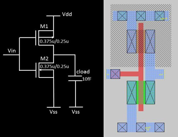

For KR > 1 the NMOS current drive is greater and it forces vI VDD/2 Microelectronic Circuit Design McGraw-Hill.The simulation result shows the varying VTC of the inverter as KN/KP = KR is changed.The minimum voltage supply for a certain MOS technology is 2VT∙ln(2) Microelectronic Circuit Design McGraw-Hill.The simulation result shows the varying VTC of the inverter as VDD is changed.Region 1: vO = VH vI VDD – |VTP| Microelectronic Circuit Design McGraw-Hill.The VTC shown is for a CMOS inverter that is symmetrical (KP = KN).Notice that VH = 5V and VL = 0V, and that ID = 0A which means that there is no static power dissipation Microelectronic Circuit Design McGraw-Hill.The figure shows the two modes of static operation with the circuit and simplified models.Static Characteristics of the CMOS Inverter Polysilicon is used to form common gate connections, and metal is used to tie the two drains together Microelectronic Circuit Design McGraw-Hill.The PMOS transistors lie within the n-well, whereas the NMOS transistors lie in the p-substrate.Two methods of laying out a CMOS inverter are shown.When vI is pulled low (VSS), the NMOS inverter is turned off, while the PMOS is turned on pulling the output up to VDD Microelectronic Circuit Design McGraw-Hill.When vI is pulled high (VDD), the PMOS inverter is turned off, while the NMOS is turned on pulling the output down to VSS.Simplified operation model with a low input applied Microelectronic Circuit Design McGraw-Hill.Simplified operation model with a high input applied.To accomplish this, the technique of “n-well” implantation is needed as shown in the figure which shows the cross-section of a CMOS inverter Microelectronic Circuit Design McGraw-Hill.The CMOS inverter consists of a PMOS stacked on top on a NMOS, but they need to be fabricated on the same wafer.CMOS still dominates digital IC design today Microelectronic Circuit Design McGraw-Hill.The concept of CMOS was introduced in 1963 by Wanlass and Sah, but it did not become common until the 1980’s as NMOS microprocessors were dissipating as much as 50 W and alternative design technique was needed.Complementary MOS, or CMOS, needs both PMOS and NMOS devices for their logic gates to be realized.Discuss the concept of “latchup” Microelectronic Circuit Design McGraw-Hill.Introduce design techniques for “cascade buffers”.Introduce dynamic logic and domino CMOS logic techniques.Present expressions for dynamic performance of CMOS logic devices.Discuss static and dynamic power in CMOS logic.Learn to design basic and complex logic gates.Explore the voltage transfer characteristics CMOS inverters.Blalock Microelectronic Circuit Design McGraw-Hill Chapter 7Complementary MOS (CMOS) Logic Design Microelectronic Circuit Design Richard C.


 0 kommentar(er)
